Boundary Scan Tests
Automatically generated and manually created tests
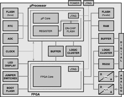
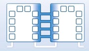
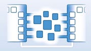
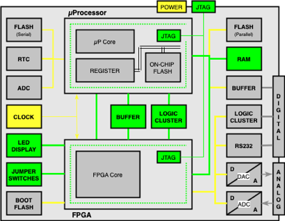
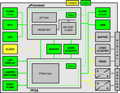
Example: Block diagram of a complex board …
including two Boundary Scan Devices, - one µProcessor and one FPGA - and several Non- Boundary Scan Devices and different types of Interfaces (POWER, JTAG, DIGITAL, ANALOG)
Before the Boundary Scan System can generate the tests the CAD data (parts list, nets list) have to be imported. Models have to be assigned for the Boundary Scan Devices (BSDL-Files) and also for the Non Boundary Scan Devices.
A boundary scan test project contains different test types. Several tests are automatically generated based on the imported board data. Other tests can be created manually. In order to run the tests, the board must be supplied with Power and the JTAG interface must be connected to the Boundary Scan Controller.
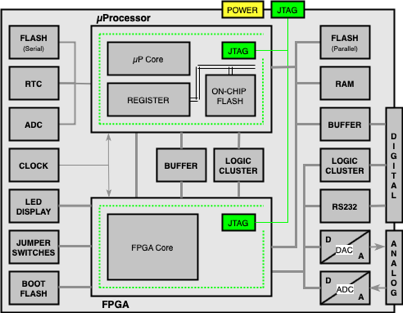
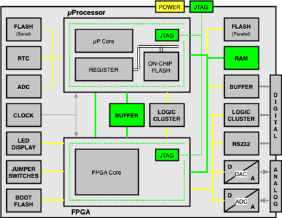
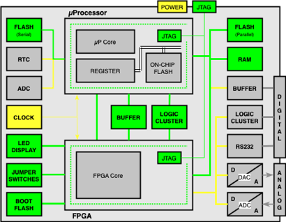
Infrastructure Test
This test is usually the first test used to verify the JTAG interface. This test tests the internal registers of the Boundary Scan Devices such as IDCODE and USERCODE registers (if available) as well as the BYPASS and the BOUNDARY registers. If this test is passed the JTAG interface is fully tested.
The power supply is also tested indirectly (not fully testable).
fully testable
not fully testable
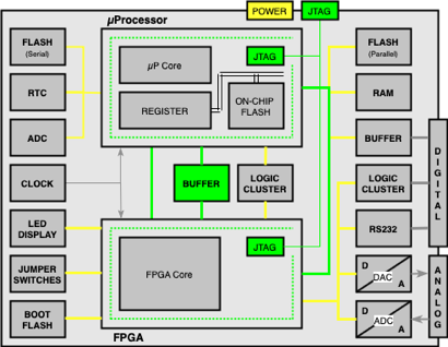
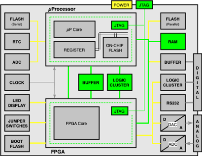
Interconnection Test
This test tests the connections between the Boundary Scan Devices, direct connections as well as connections over buffers will be fully tested.
Pull-up and Pull-down resistors can also be tested for presence.
For Boundary Scan Nets with only one connected Boundary Scan pin this test can find out shorts, but no opens.
fully testable
not fully testable
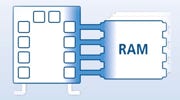
Memory Access Tests
This test tests the connections between the Boundary Scan Device(s) and the Memory Different kind of memory devices such as SRAM, DRAM, DDR RAM, DPRAM are supported.
The test realises read and write cycles to different addresses with different data.
Failures on Address and Data lines can be diagnosed on pin and net level.
fully testable
(Logic) Cluster Tests
The test for logic clusters can be generated automatically (in case there are included only logic gates and no flip flops).
Otherwise this test can be created manually for any kind of clusters, connected to Boundary Scan Devices, in different ways (Description of the Cluster as Truth Table or Wave Form or using a basic script language.
fully testable
Create Manual Tests
Manual tests are usually created to test small areas of the board, as most tests are generated automatically.
Typical applications are:
- Check of Clocks (Toggling or not toggling?)
- Control of LEDs or Displays
- Measurement of the jumper settings or switch settings
Manual tests can involve interactions with the operator.
not fully testable
fully testable
Flash Access Tests
If the Flash Devices are connected to Boundary Scan Devices they can be accessed. A simple test is to readout for example the manufacturer and device code.
Several types of flashes such as NAND and NOR flashes are supported.
Also serial flashes with I2C, µWire, SPI or other serial interface protocols are supported.
Boot flashes for FPGA configuration are also supported.
fully testable
Test of Serial Devices
There are library models for such devices that support the different protocols (I2C, µWire, SPI, ...). Write and read operations can be easily implemented on this basis. This makes it relatively easy to test such devices.
- Typical applications are
- Serial ADCs and DACs
- Real Time Clocks (RTC)
- Sensors (e.g. temperature sensors)
- Serial to Parallel or Parallel to Serial converters
fully testable
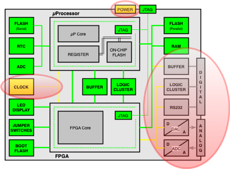
Test Coverage (no access to the interfaces)
The Test Coverage is already very good, but can be further improved.
Modern Boundary Scan Test Systems also enable the measurement of analog Voltages (POWER) and Frequencies (CLOCK).
There are various solutions to test the digital and analog interfaces:
- Connecting these interfaces with additional Boundary Scan resources
- Combining with a 3rd party tester such as ICT or Flying Probe tester
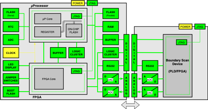
Test Coverage (with access to the interfaces)
Test Adapter Board
The test adapter board can be connected via cables or via a simple test fixture.
TECOSERV can develop the test adapter board according to your requirements. This method is recommended if your boards have the same interfaces for several products. Of course, you can do this on your own or with the support of TECOSERV.
There are many universal test adapter boards on the market. There are also a large number of such boards for standardised interfaces such as PCI or PCIe interfaces or for different types of memory sockets.
Contact TECOSERV to find the best solution for your requirements